1. Notation and Units
Symbol |
Description |
SI |
British |
|
| A | aspect ratio | |||
| a, b | construction lengths (see Sketch 1.6c) | m | ft | |
| a1 | lift-curve slope of basic wing | rad−1 | rad−1 | |
| (a1)0 | lift-curve slope of basic aerofoil | rad−1 | rad−1 | |
| Calc | input entry to select calculation procedure (see Table 3.1 or Sketch 3.1) | |||
| CL | lift coefficient; (lift)/qS for wing, (lift)/qc for aerofoil | |||
| CLm | maximum lift coefficient of aerofoil with high-lift devices deployed | |||
| CLmB | maximum lift coefficient of basic aerofoil (high-lift devices not deployed) | |||
| ΔCLm | increment in aerofoil maximum lift coefficient due to deployment of high-lift devices | |||
| ΔCLml | increment in aerofoil maximum lift coefficient due to deployment of leading-edge device | |||
| ΔCLmt | increment in aerofoil maximum lift coefficient due to deployment of trailing-edge flap | |||
| CLmaxB | maximum lift coefficient of basic wing (high-lift devices not deployed) | |||
| CLmaxBf | maximum lift coefficient of basic wing-fuselage combination (high-lift devices not deployed) | |||
| CLmaxw | maximum lift coefficient of wing with high-lift devices deployed | |||
| CLmaxwf | maximum lift coefficient of wing-fuselage combination with high-lift devices deployed | |||
| ΔCLmax | increment in wing maximum lift coefficient due to deployment of high-lift devices | |||
| ΔCLmaxf | increment in maximum lift coefficient due to fuselage | |||
| ΔCLmaxl | increment in wing maximum lift coefficient due to deployment of leading-edge devices | |||
| ΔCLmaxt | increment in wing maximum lift coefficient due to deployment of trailing-edge flaps | |||
| CL0 | aerofoil lift coefficient at zero angle of attack with high-lift devices deployed | |||
| ΔCL0 | increment in aerofoil lift coefficient at zero angle of attack due to deployment of high-lift devices | |||
| ΔCL0l | increment in aerofoil lift coefficient at zero angle of attack due to deployment of leading-edge device | |||
| ΔCL0t | increment in aerofoil lift coefficient at zero angle of attack due to deployment of trailing-edge flap | |||
| CL0B | lift coefficient at zero angle of attack for basic aerofoil (high-lift devices not deployed) | |||
| CL0Bf | lift coefficient at zero angle of attack for basic wing-fuselage combination (high-lift devices not deployed) | |||
| CL0Bw | lift coefficient at zero angle of attack for basic wing (high-lift devices not deployed) | |||
| CL0w | lift coefficient of wing at zero angle of attack with high-lift devices deployed | |||
| CL0wf | lift coefficient of wing-fuselage combination at zero angle of attack with high-lift devices deployed | |||
| ΔCL0w | increment in wing lift coefficient at zero angle of attack due to deployment of high-lift devices | |||
| ΔCL0lw | increment in wing lift coefficient at zero angle of attack due to deployment of leading-edge devices | |||
| ΔCL0tw | increment in wing lift coefficient at zero angle of attack due to deployment of trailing-edge flaps | |||
| c | chord of basic aerofoil; local chord of basic wing | m | ft | |
| c´ | extended chord, ie chord with high-lift devices deployed | m | ft | |
| c̿ | aerodynamic mean chord of basic wing | m | ft | |
| cl | chord of leading-edge device (see Sketches 1.4 and 1.6) | m | ft | |
| Δcl | chord extension due to deployment of leading-edge devices (see Sketches 1.4 to 1.6) | m | ft | |
| cl´ | extended chord of leading-edge device (see Sketches 1.4 to 1.6) | m | ft | |
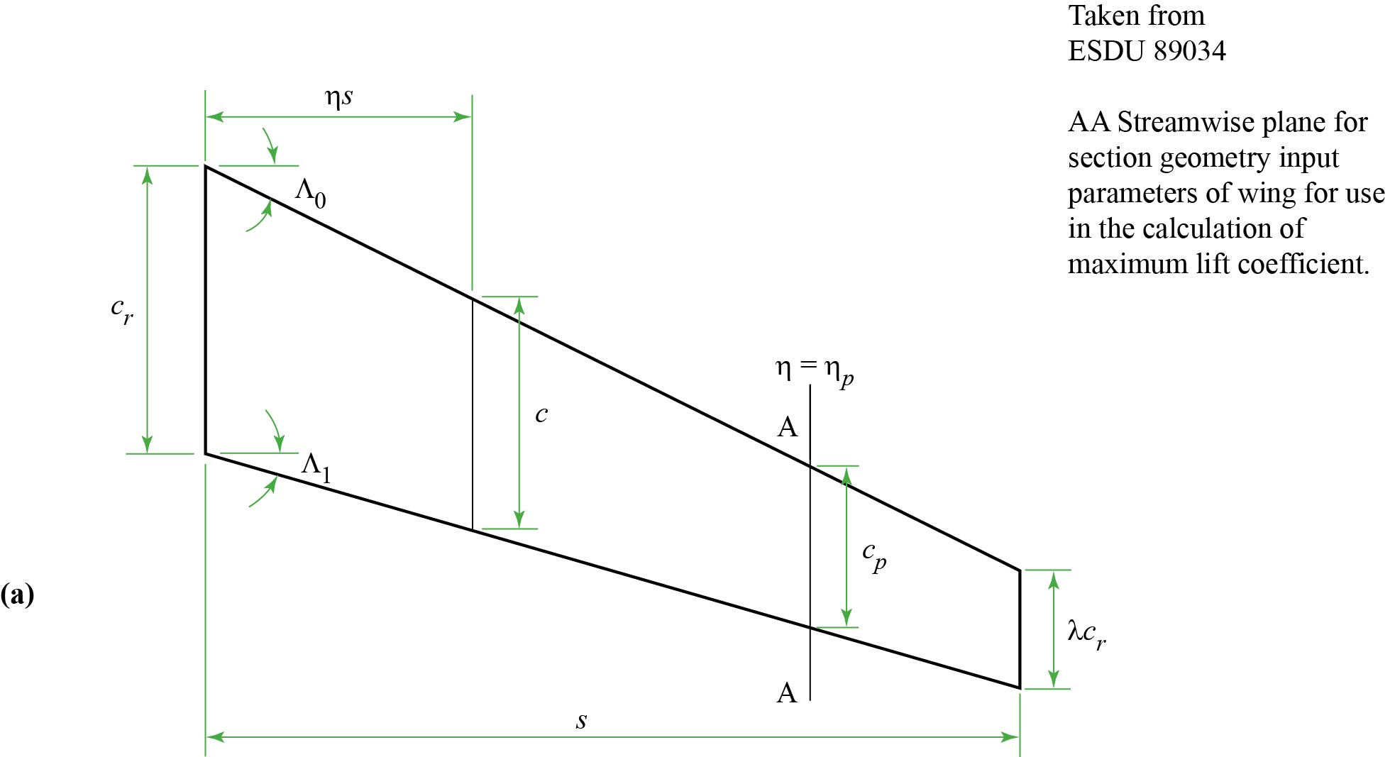
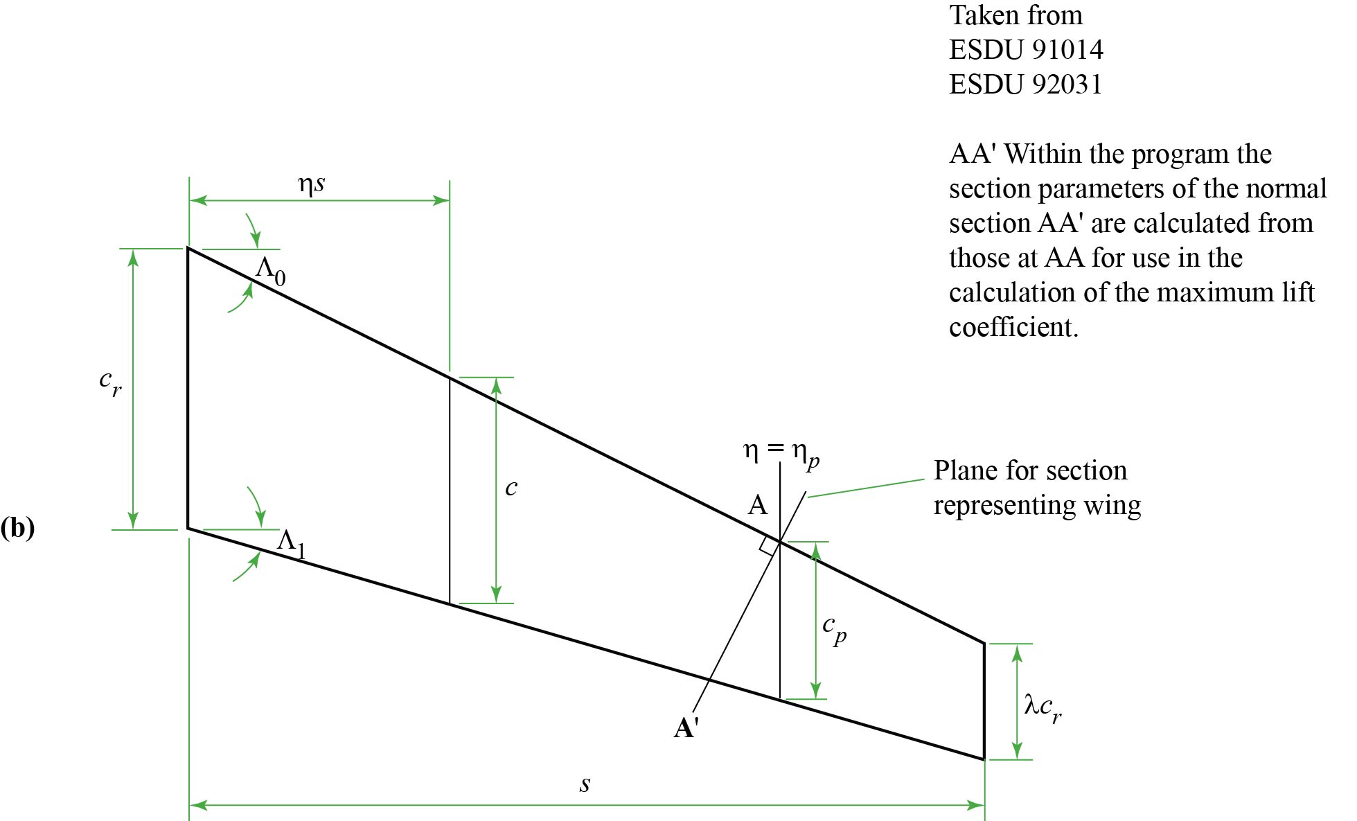
| cp | wing chord at η = ηp (see Sketch 1.2a) | m | ft | |
| cr | wing root (centre-line) chord | m | ft | |
| ct | chord of trailing-edge flap (see Sketches 1.7 and 1.8) | m | ft | |
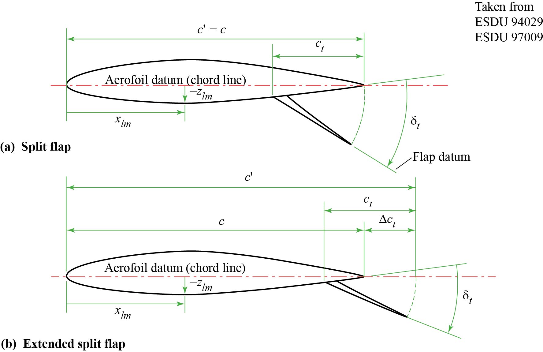
| Δct | chord extension due to deployment of trailing-edge flaps (see Sketches 1.7 and 1.8) | m | ft | |
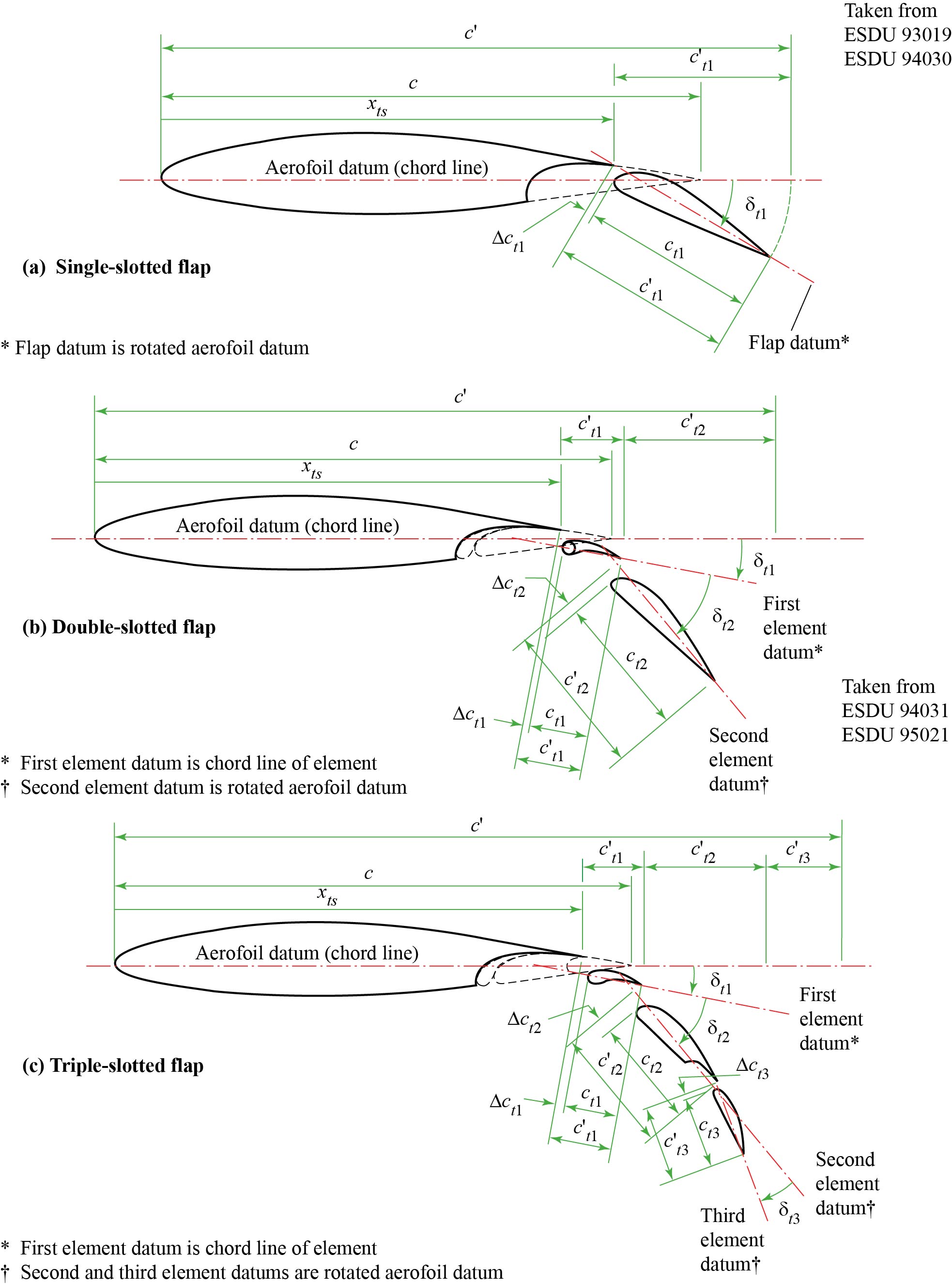
| ct1,ct2,ct3 | chord of first, second and third elements of slotted trailing-edge flap system (see Sketch 1.9) | m | ft | |
| c´t1,c´t2,c´t3 | extended chord of first, second and third elements of slotted trailing-edge flap system (see Sketch 1.9) | m | ft | |
| Δct1,Δct2,Δct3 | chord extension due to deployment of first, second and third elements of slotted trailing-edge flap system (see Sketch 1.9) | m | ft | |
| Gl | slat or vented Krueger gap; distance between device trailing-edge and section surface, measured normal to the surface (see Sketches 1.6a and 1.6b) | m | ft | |
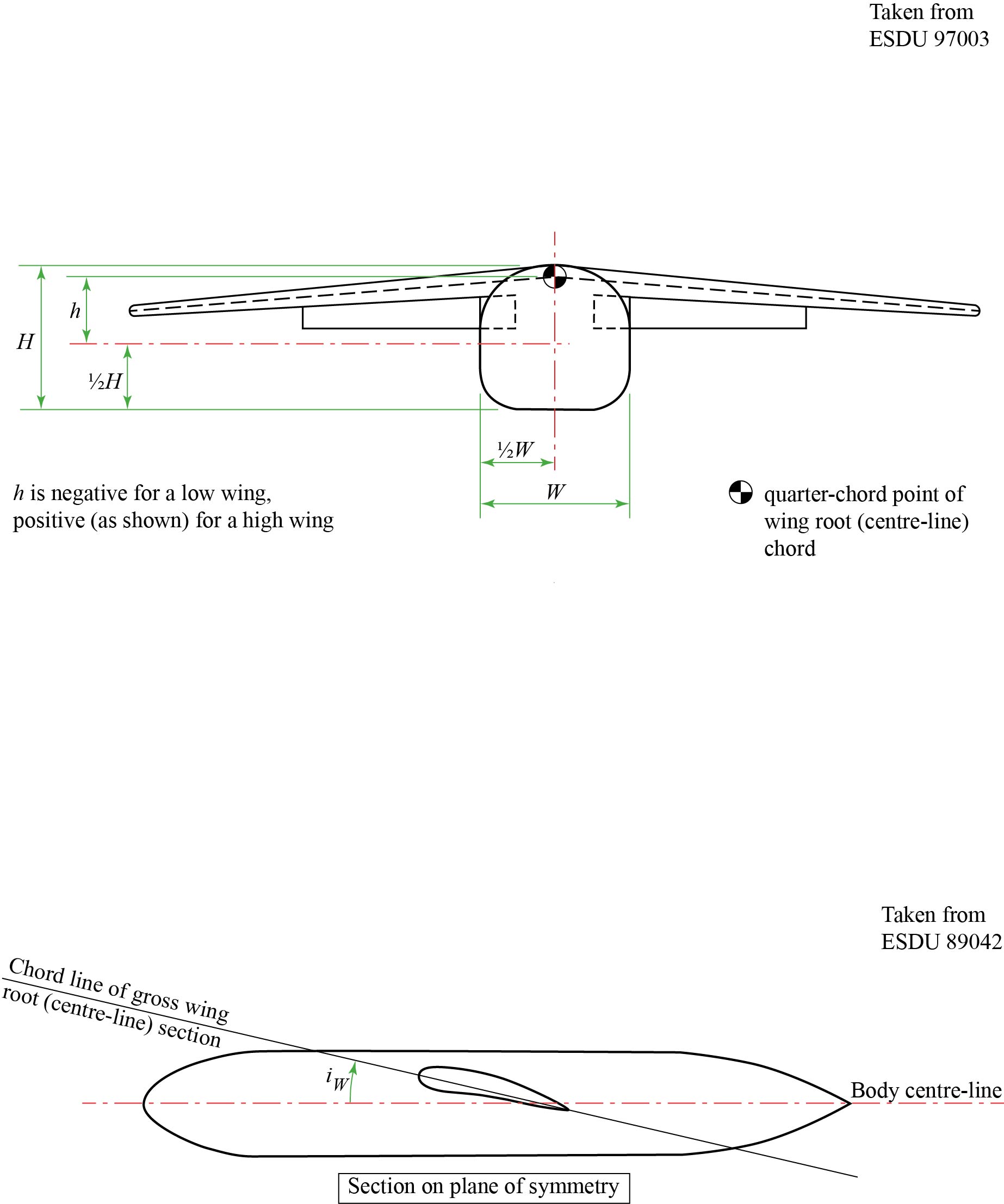
| H | fuselage height (see Sketch 1.10) | m | ft | |
| Hl | height of slat or vented Krueger flap above section chord line (see Sketches 1.6a and 1.6b) | m | ft | |
| h | height of quarter-chord point of wing root (centre-line) chord above fuselage longitudinal centre-line (see Sketch 1.10) | m | ft | |
| iW | angle between chord line of wing root (centre-line) section and fuselage longitudinal centre-line (see Sketch 1.10) | deg | deg | |
| Ll | overlap between deployed slat or vented Krueger flap trailing-edge and fixed-section nose (see Sketches 1.6a and 1.6b) | m | ft | |
| M | free-stream Mach number | |||
| Mk | free-stream Mach number values entered under Flow Data section of UI (up to NMR comma-separated values are permitted) | |||
| Nl | integer indicating the type of a leading-edge device | |||
| NMR | the number of Mach number, Reynolds number pairs provided 1 ≤ NMR ≤ 10 |
|||
| Nnl | number of leading-edge device panels on each (half-) wing 1 ≤ Nnl ≤ 5 |
|||
| Nnt | number of trailing-edge flap panels on each (half-) wing 1 ≤ Nnt ≤ 5 |
|||
| Nt | integer indicating the type of a trailing-edge flap | |||
| Nδl | number of deflection angle settings of leading-edge devices | |||
| Nδt | number of deflection angle settings of trailing-edge flaps | |||
| n | denotes nth chord line (0 ≤ n ≤ 1), n = 0 indicates leading edge; n = 1 indicates trailing edge | |||
| q | free-stream kinetic pressure | N/m2 | lbf/ft2 | |
| Rc | Reynolds number based on c | |||
| Rc̿ | Reynolds number based on c̿ | |||
| Rk | Reynolds number values entered under Flow Data section of UI (Rc for aerofoils; Rc̿ for wings, up to NMR comma-separated values are permitted) | |||
| S | wing planform area | m2 | ft2 | |
| s | semi-span | m | ft | |
| t | section maximum thickness | m | ft | |
| tb | section thickness at trailing edge | m | ft | |
| W | fuselage width (see Sketch 1.10) | m | ft | |
| x | general chordwise station measured streamwise from leading edge of section, positive aft (see Sketch 1.1d) | m | ft | |
| xcm | chordwise location of zcm (see Sketch 1.1d) | m | ft | |
| xl | chordwise location of undeployed slat trailing edge (see Sketch 1.6a) | m | ft | |
| xlm | chordwise location of zlm (see Sketch 1.8) | m | ft | |
| xn | chordwise location of fixed-section nose (see Sketch 1.6a) | m | ft | |
| xtr | chordwise location of boundary-layer transition (same location assumed on both surfaces) | m | ft | |
| xts | chordwise location of flap-shroud trailing edge (see Sketch 1.9) | m | ft | |
| xum | chordwise location of zum (see Sketch 1.1d) | m | ft | |
| xτ | chordwise location of trailing edge of cl´ for deployed Krueger flaps and sealed slats (see Sketch 1.5) | m | ft | |
| z | general section ordinate, positive above chord line | m | ft | |
| zcm | maximum height of camber line of basic aerofoil or wing section (see Sketch 1.1d) | m | ft | |
| zc50 | camber-line ordinate at x/c = 0.5 | m | ft | |
| zc92 | camber-line ordinate at x/c = 0.92 | m | ft | |
| zh | vertical location of hinge-line for drooped leading edge (see Sketch 1.4) | m | ft | |
| zl | lower surface ordinate, negative below chord line | m | ft | |
| (zl/c)ξ | value of zl/c at x = ξc/100 | |||
| zlm | maximum (negative) lower surface ordinate (see Sketch 1.8) | m | ft | |
| zu | upper surface ordinate, positive above chord line | m | ft | |
| (zu/c)ξ | value of zu/c at x = ξc/100 | |||
| zum | maximum upper surface ordinate (see Sketch 1.1d) | m | ft | |
| α | angle of attack of aerofoil or wing root (centre-line) chord | deg | deg | |
| αCLm | angle of attack for CLm | deg | deg | |
| αCLmaxw | angle of attack for CLmaxw | deg | deg | |
| αCLmaxwf | angle of attack for CLmaxwf | deg | deg | |
| α0Bw | zero-lift angle of attack for basic wing (high-lift devices not deployed) | deg | deg | |
| α0wf | zero-lift angle of attack for wing-fuselage combination with high-lift devices deployed | deg | deg | |
| δl | deflection angle of leading-edge device (see Sketches 1.4 to 1.6) | deg | deg | |
| δt | deflection angle of trailing-edge flap, positive trailing-edge-down (see Sketches 1.7 and 1.8) | deg | deg | |
| δt1,δt2,δt3 | deflection angle of first, second and third element of slotted trailing-edge flap system relative to datum of preceding element, positive trailing-edge-down (see Sketch 1.9) | deg | deg | |
| δ2/3 | twist angle of wing chord at η = 2/3, positive nose-up | deg | deg | |
| η | spanwise distance from wing root (centre-line) chord as a fraction of semi-span | |||
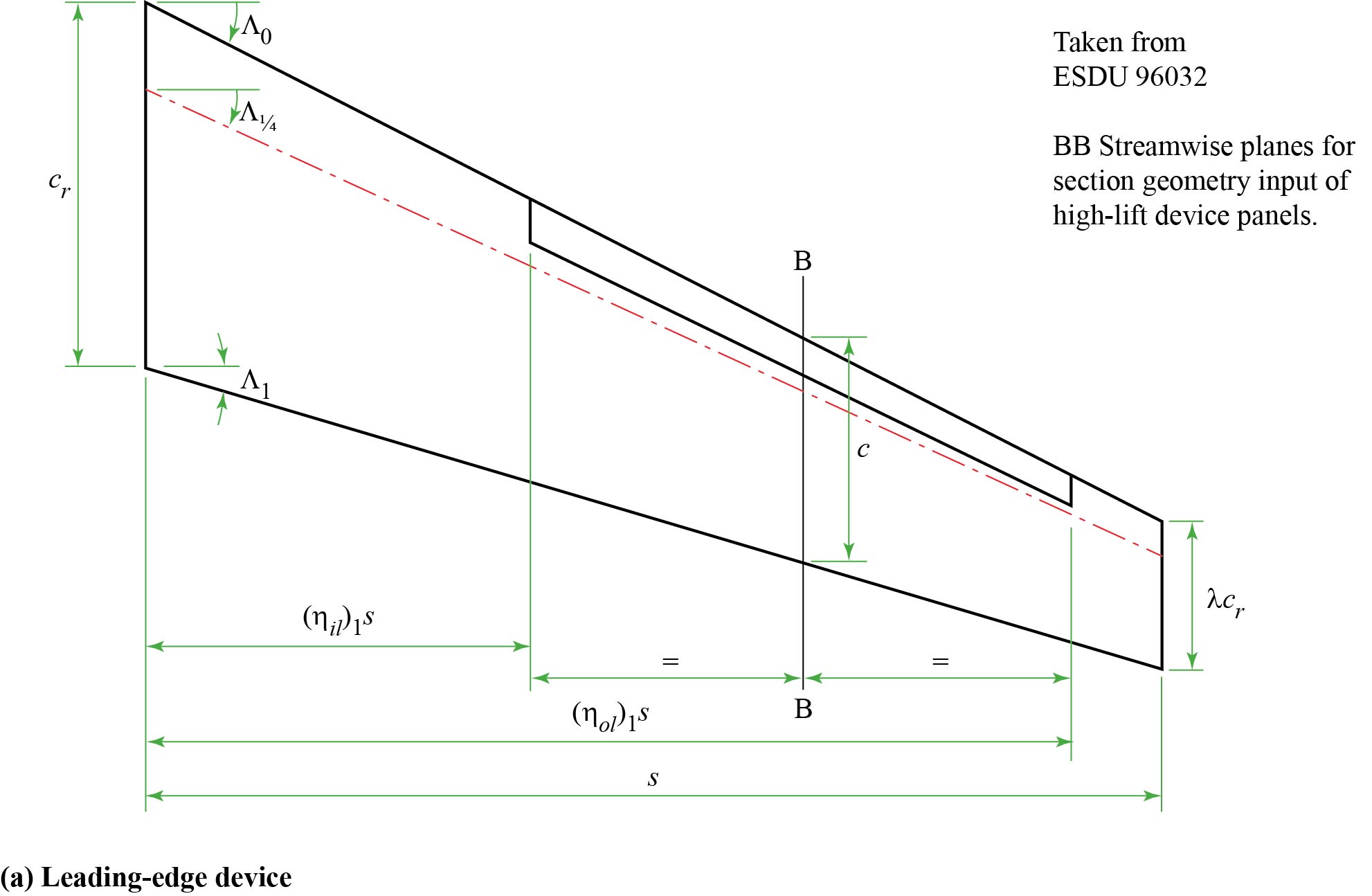
| (ηil)j, (ηol)j | values of η for respective inboard, outboard limits of jth leading-edge device panel | |||
| (ηit)j, (ηot)j | values of η for respective inboard, outboard limits of jth trailing-edge flap panel | |||
| ηp | value of η for section of basic wing with peak loading due to angle of attack (see Sketch 1.2 and this note). | |||
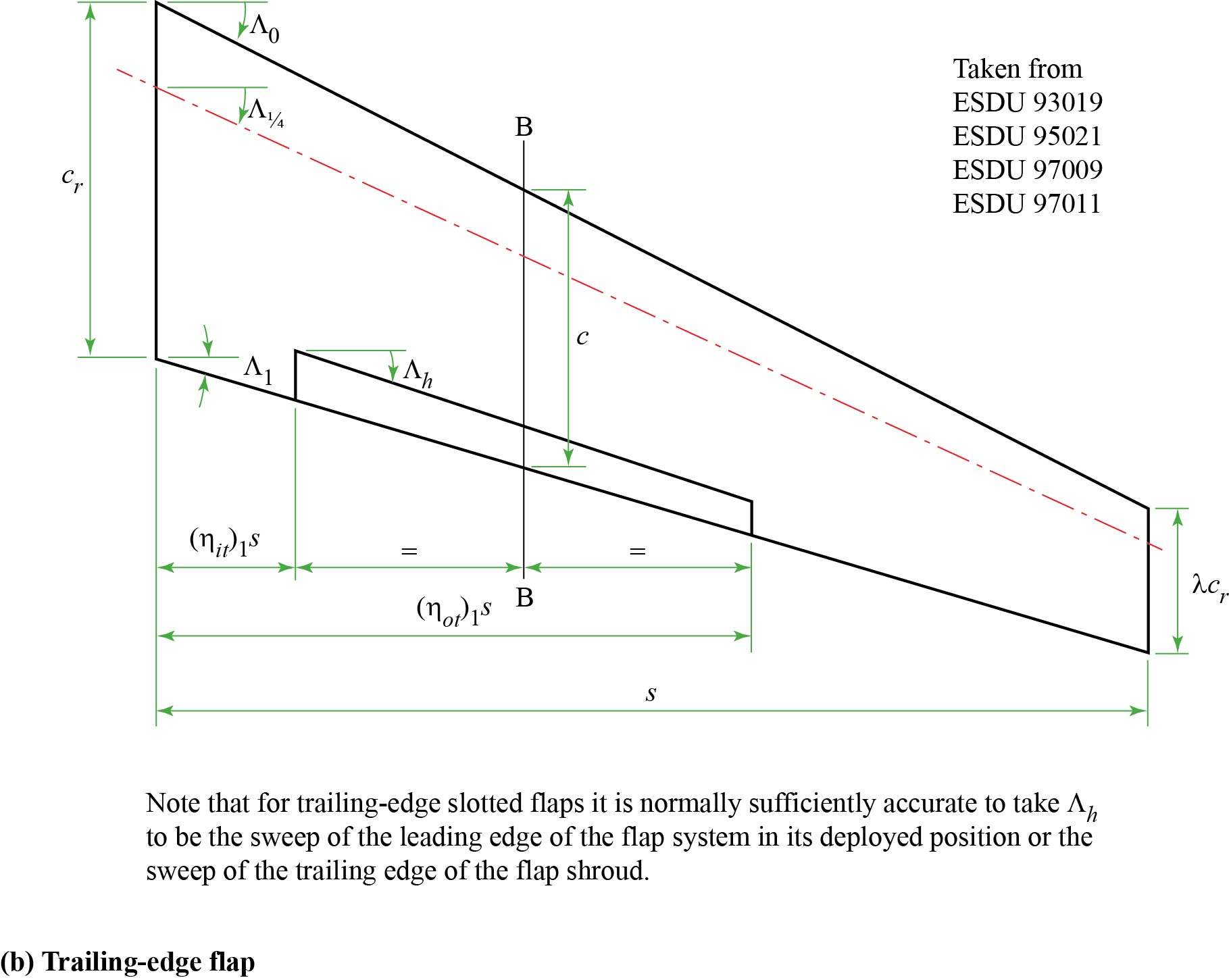
| Λh | hinge-line sweep of trailing-edge flaps (see Sketch 1.3b) | deg | deg | |
| Λn | sweep of nth chord line of basic wing (in degrees, positive aft) | deg | deg | |
| λ | wing taper ratio, tip chord/root (centre-line) chord | |||
| ξ | dimensionless coordinate, ξ = 100 x/c | |||
| ρl | leading-edge radius (see Sketches 1.4 to 1.6) | m | ft | |
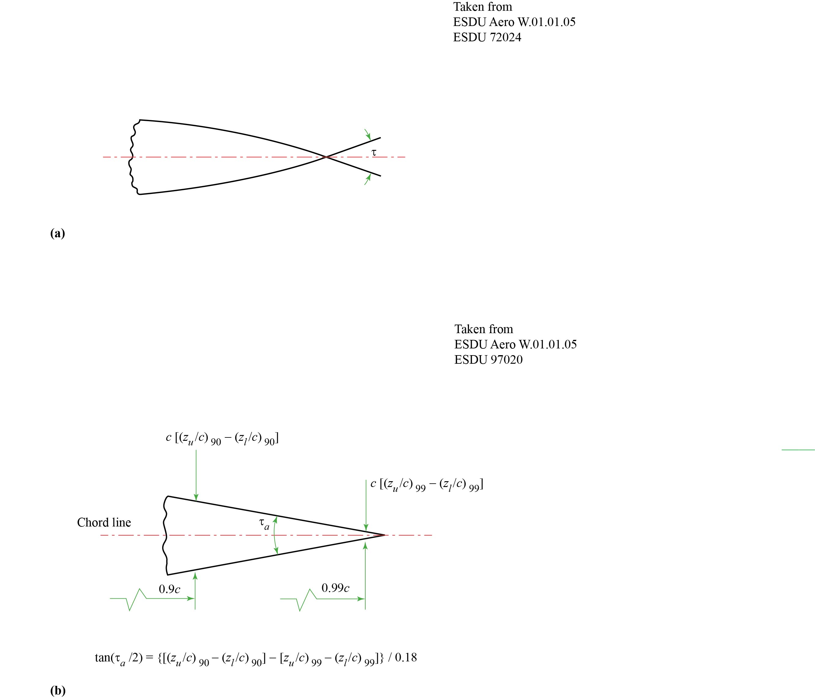
| τ | trailing-edge angle (see Sketch 1.1a) | deg | deg | |
| τa | trailing-edge angle (see Sketch 1.1b) | deg | deg | |
| τau | trailing-edge angle (see Sketch 1.1c) | deg | deg | |
| τu | aerofoil upper-surface angle (see Sketch 1.1d) | deg | deg | |
| ϕt | angle between aerofoil datum and tangent to upper surface at trailing edge (see Sketch 1.7a) | deg | deg | |
| Subscripts | ||||
| i, k | dummy integer variables | |||
| j |
as in ( )j, denotes values associated with device panels. 1 ≤ j ≤ Nnl, 1 ≤ j ≤ Nnt Section properties are taken at panel mid-span. |
|||
| r | as in ( )r, denotes values associated with root (centre-line) section. | |||
| 2/3 | as in ( )2/3, denotes values associated with section at η = 2/3. | |||
| Acronymic terms used | ||||
| LED | Leading-edge device | |||
| TED | Trailing-edge device (flap) | |||
| UI | User-interface | |||
Sketch 1.1 Aerofoil Geometry

Sketch 1.2 Wing Notation
Sketch 1.3 Wing Notation with Devices Undeployed (Single Panel)
Sketch 1.4 Plain leading-edge flaps and drooped leading edges (see explanatory notes below)
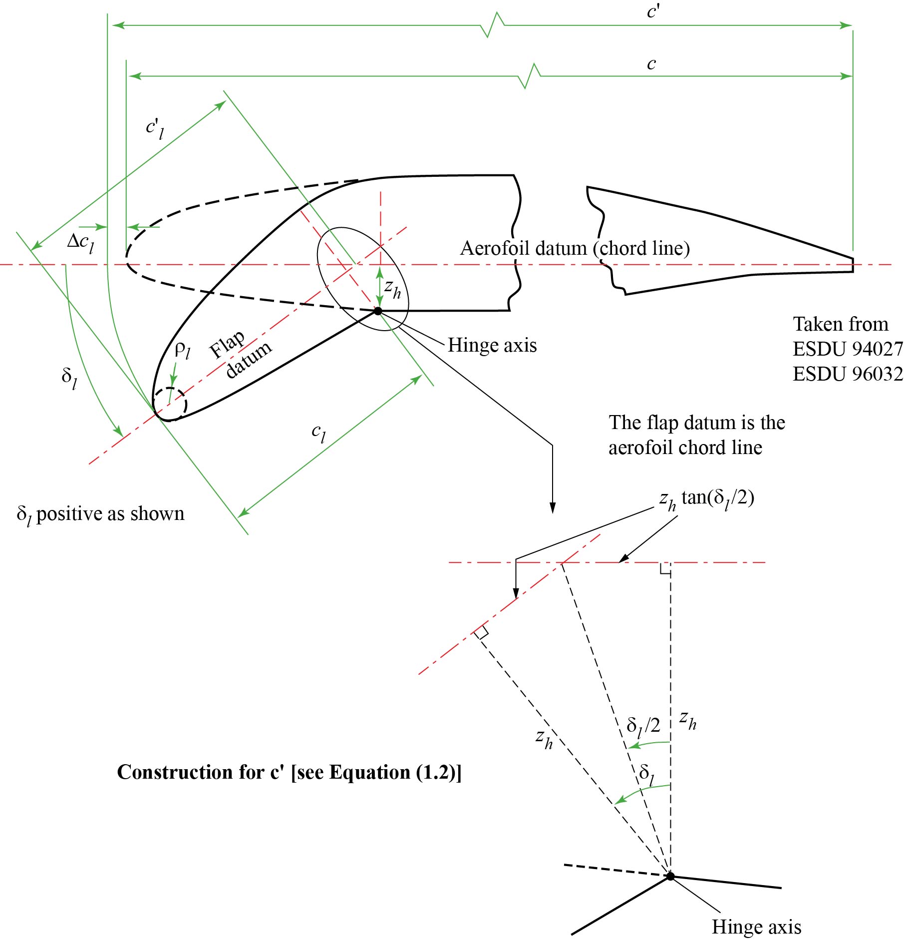
From the sketch,
| cl´ = cl + zh tan (δl/2) | (1.1) | ||
| and | c´ = c + 2 zh tan (δl/2) | (1.2) |
Equations (1.1) and (1.2) relate to the specific type of device shown in the sketch, i.e. a device deployed by rotation around a lower-surface hinge. Many variations in design are possible and the corresponding values of cl´ and c´ appropriate to any other arrangement used would have to be determined.
Sketch 1.5 Krueger flaps and sealed slats (see explanatory notes below)
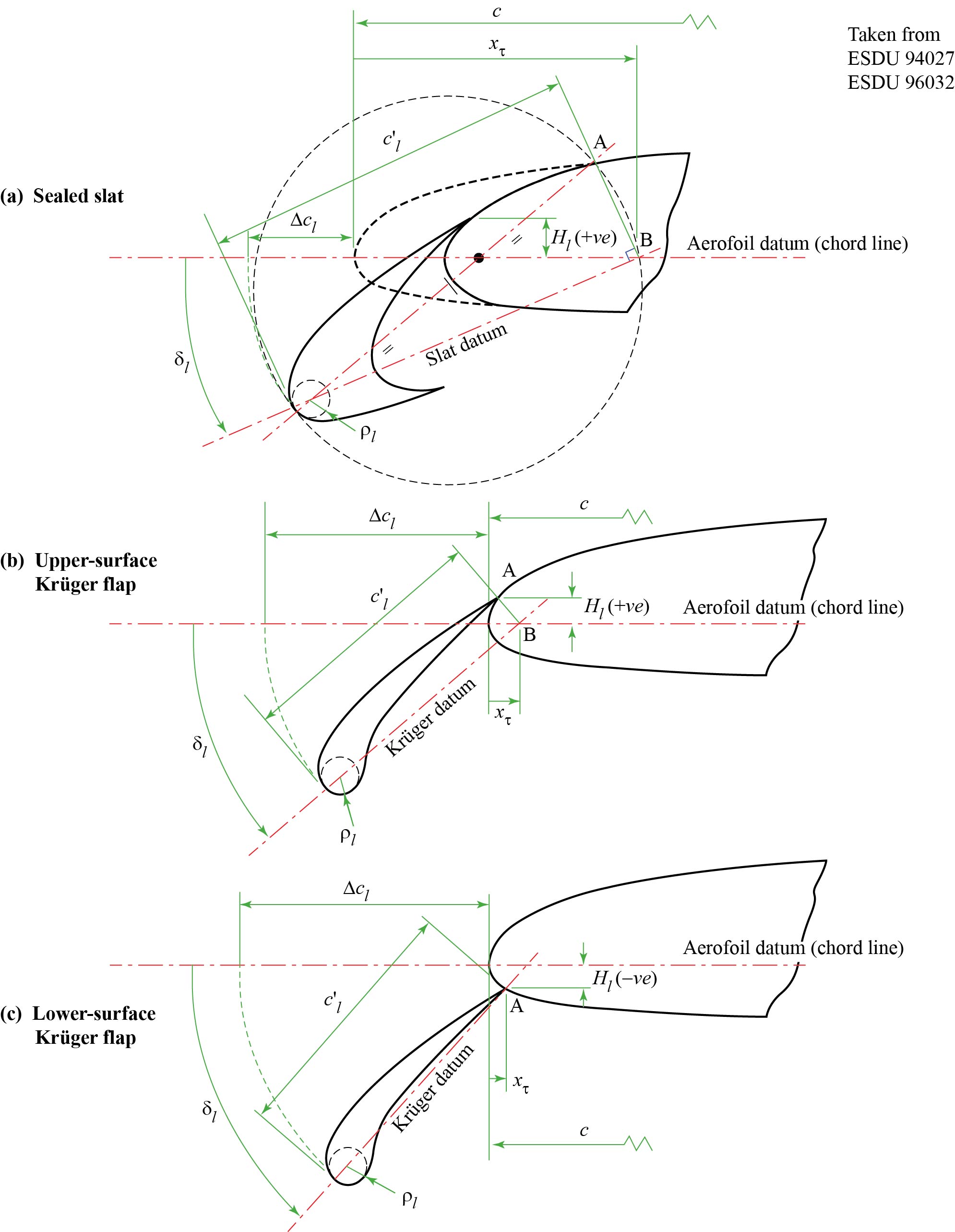
Krüger flaps and sealed slats have no slot and are therefore quite similar, in terms of their operation, to plain leading-edge flaps; the method for predicting ΔCL0l is likewise similar. Care is, however, required for the definition of equivalent flap chord, cl´ and deflection angle, δl. Sketches 1.5(a) to 1.5(c) show how they are defined for sealed slats and two forms of Krüger flap, termed upper-surface and lower-surface Krüger flaps.
For the sealed slat and upper-surface Krüger flap the equivalent leading-edge flap is taken to be related to that part of the aerofoil and flap forward of the point at which the section first departs from the original upper-surface profile due to the deployment of the flap, i.e. points A on Sketches 1.5(a) and 1.5(b). The flap chord and deflection consistent with this are shown on those sketches. There is of necessity a small difference in the definitions for the case of the lower-surface Krüger flap, see Sketch 1.5(c).
Sealed slats and upper-surface Krüger flaps (Sketches 1.5(a) and 1.5(b))
For sealed slats and upper-surface Krüger flaps the values of cl´ and δl for the equivalent plain flap are obtained as follows. A straight line is drawn from the leading edge, passing through the centre of the flap leading-edge radius to point A, the point of departure from the original aerofoil surface. A circle centred on the mid-point of this line intersects the basic aerofoil chord at point B. The straight line joining B to the flap leading edge and passing through the centre of the flap leading-edge radius defines the equivalent plain flap chord, cl´. The angle between that chord and the aerofoil chord defines δl.
Lower-surface Krüger flap (Sketch 1.5(c))
For a lower-surface Krüger flap, where the flap trailing-edge is on the aerofoil lower surface, the chord cl´ is taken as the length of the line drawn from A to the leading edge of the flap, passing through the centre of the flap leading-edge radius. The angle between that chord and the aerofoil chord defines δl.
| c´ = c + Δcl | = c + cl´ − xτ | (1.3) |
Sketch 1.6 Slats and vented Krueger flaps (see explanatory notes below)
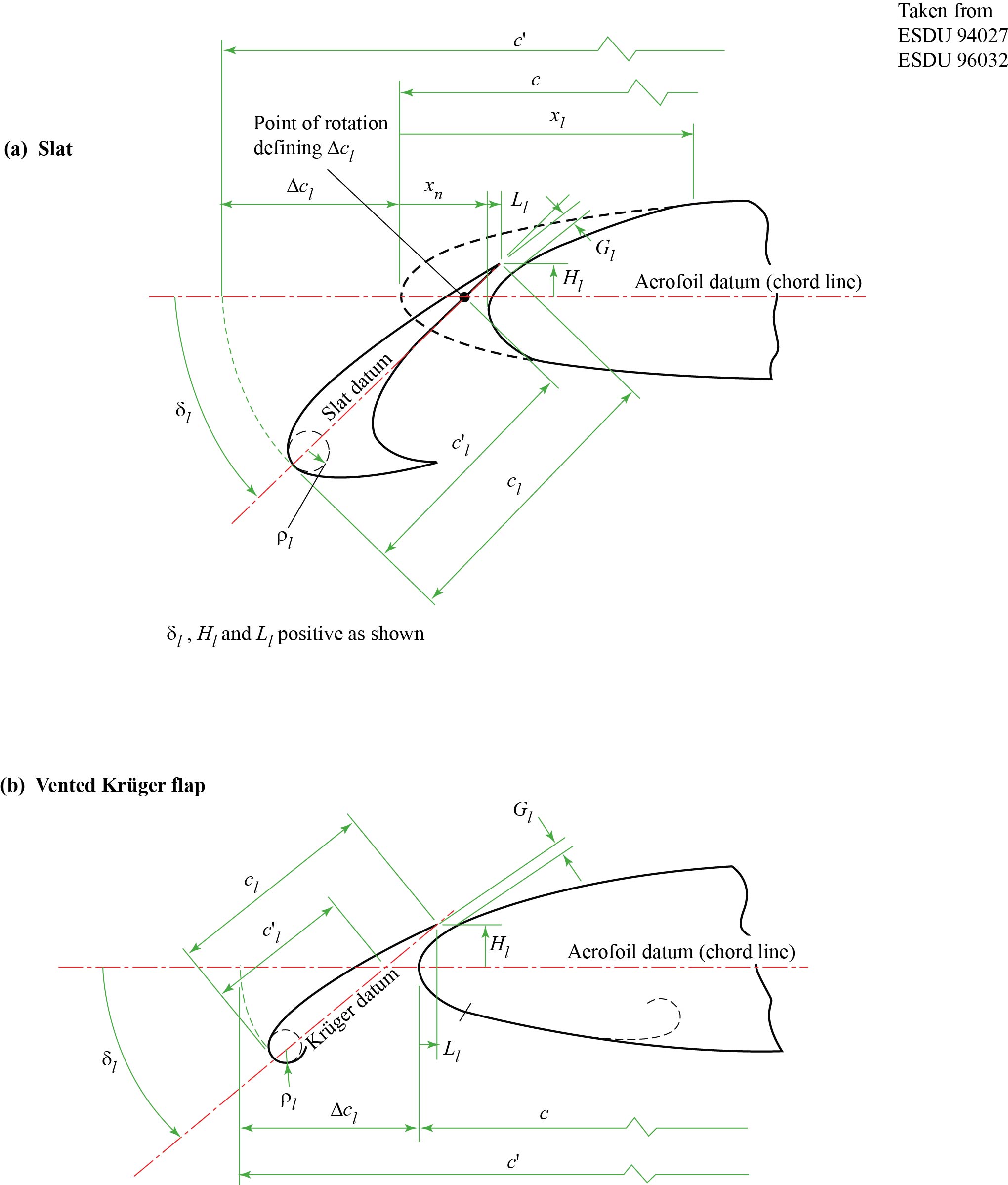

The deflection, δl, of both slats and vented Krüger flaps is defined using the angle between the datum chords of the slat (or flap) and the aerofoil. The slat (or flap) datum chord is defined using the line passing through the centre of the leading-edge radius and the slat (or flap) trailing edge. The extended chord, c´, and the chord extension, Δcl, are defined by rotating the slat (or flap) about the intersection of the slat (or flap) and aerofoil datum chords, as shown in the sketch.
In Sketches 1.6(a) and 1.6(b), for a slat and vented Krüger flap
| cl´ | = cl − Hl cosec δl | (1.4) |
For a slat, the geometry in Sketch 1.6(a) gives
| c´ | = c + Δcl | ||
| = c + cl − xn − Ll − b | |||
| = c + cl − xn − Ll − Hl tan (δl/2) | (1.5a) |
For a vented Krüger flap, the geometry in Sketch 1.6(b) gives
| c´ | = c + Δcl | ||
| = c + cl − Ll − b | |||
| = c + cl − Ll − Hl tan (δl/2) | (1.5b) |
Sketch 1.7 Plain trailing-edge flap
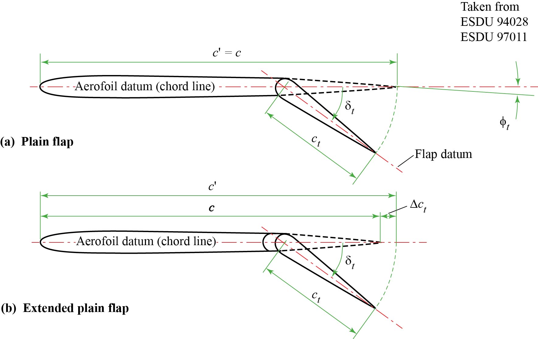
Sketch 1.8 Split flap
Sketch 1.9 Slotted flaps
Sketch 1.10 Wing-fuselage geometry
2. Introduction
Details are provided of a program, originally released as ESDUpac A9931 and here reissued incorporating a modern graphical UI as the ESDU Lift Curve Aerodynamics suite (LiCrA). The program calculates the maximum lift coefficient, the lift coefficient at zero angle of attack and the lift curve of aerofoil sections and straight-tapered wings with high-lift devices deployed at low speeds. The basic wing (no devices deployed) may have camber and twist. The program includes methods that allow for the presence of a fuselage. For completeness, calculations can be made for the aerofoil and wing when there are no high-lift devices deployed but the prediction of the shape of the non-linear part of the lift curve should be treated with caution because it employs a technique developed for use when high-lift devices are deployed*. The method is intended for use only for free-stream Mach numbers up to about M = 0.25. No allowance is made for ground effect.
An auxiliary module to the original version of the program, ESDUpac B9931, allows the prior calculation of the spanwise position of the section of the basic wing that has the peak loading due to angle of attack. It is necessary to know that section because full runs of the main program for wings and wing-fuselage combinations require its geometry. When using the LiCrA UI, since the spanwise peak loading position calculation is seamlessly incorporated there is no need for it to be run separately.
A companion program described in ESDU 930158 allows calculations of the maximum lift coefficient to be made for a basic wing for subcritical Mach numbers. The program introduced in ESDU 93015 also permits aerofoil characteristics to be calculated for Mach numbers up to 0.4. However, neither the lift coefficient at zero angle of attack nor the general shape of the lift curve is estimated.
The methods employed within the program to determine the maximum lift coefficient and the lift coefficient at zero angle of attack are those given in ESDU 840263 and ESDU 9402710 to ESDU 9403114 for aerofoils with and without high-lift devices and in ESDU 890344 and ESDU 910146, ESDU 920317, ESDU 930199, ESDU 9502115, ESDU 9603217, ESDU 9700919 and ESDU 9701120 for wings with and without high-lift devices. The method of ESDU 9600316 is used to calculate the lift curve. The calculation of the zero-lift incidence, the lift-curve slope and the lift coefficient at zero angle of attack for a basic aerofoil or wing section are made using ESDU 720242, ESDU 9702021 and ESDU 9801122, in preference to using the more approximate methods given in other Items before ESDU 97020 and ESDU 98011 were available. This provides greater consistency throughout the program although the changes in magnitude are small and of little consequence in the overall construction of the lift curve. Some Items employ a two-dimensional lift-curve slope from ESDU Aero W.01.01.051 in the estimation of device effectiveness and the method of that Item is retained in such cases to preserve the integrity of the original correlations.
The presence of a fuselage is modelled via its effect on the zero-lift angle of attack, using the method of ESDU 890425, and through its influence on the performance of high-lift devices if they are fitted close to the fuselage side. The method of ESDU 9700318 is used to determine the fuselage effect on trailing-edge flaps. The influence of the fuselage on the performance of leading-edge devices is treated by assuming that they extend to the fuselage centre-line. For the fuselage effect on maximum lift coefficient the user must enter an increment derived from experiment or based on experience as there is no ESDU method for the prediction of that contribution, which is thought to be small.
Section 3 highlights some particular features of the programs. Section 4 describes the input files required by the programs A9931 and B9931 and Section 5 discusses the output. Section 6 lists the Derivation and References. In the printed Data Item, Section 7 provides examples of input and output files for specific cases and Appendix A presents a flow chart that gives an alternative description of the construction of input files for A9931.
* For basic aerofoils and wings the angle of attack for the onset of non-linear behaviour may be obtained from ESDU 8803023 and is dependent on section geometry and, for wings, planform geometry. At present there is no Data Item that addresses the lift curve beyond that angle of attack, but it is likely that the subsequent non-linear behaviour up to maximum lift is also dependent on section and planform geometry. These effects are masked by the additional effects associated with high-lift devices when they are deployed and are not represented in the simple fairing that models the lift curve as the maximum lift coefficient is approached. However, comparisons with a few data have shown that the use of the fairing developed for cases where devices are deployed gives an improvement over a linear assumption and, in the absence of a more detailed alternative, this is used for basic aerofoils and wings to provide an initial estimate of the curve in the non-linear range.↩
3. Program Features
For aerofoil calculations, the original version of the program, A9931, reads in all the required geometric and flow data from a single directed input file. When using A9931 for the case of a wing or a wing-fuselage combination, it is usually necessary to run the auxiliary program B9931 first in order to determine ηp, the spanwise location of the peak loading due to angle of attack for the basic wing. When using the LiCrA UI, this extra step is not necessary. Strictly, ηp varies with Mach number, but for M ≤ 0.25 the movement is sufficiently small to be neglected. It is suggested that users initially adopt a Mach number in the middle of their range of interest. With ηp known, the user can then identify the section geometry at that station and enter it as program input in the UI.
There is one special feature in the entry of the basic-section geometry in that the user may specify whether the section is of ‘conventional’ or ‘modern’ type, the latter description denoting rear-loaded sections which terminate with a small trailing-edge base thickness, incorporate large rear camber, and have a higher maximum lift coefficient than ‘conventional’ sections with the same (zu / c)1.25 and tan τu, see ESDU 840263. Alternatively, the program can be set to make the decision automatically through a test based on the geometry over the rear 10% of the section chord. If, at x / c = 0.9, (zu - zl) / zu > 0.64 and if, at the trailing-edge, tb / c > 0.004, the section is taken as ‘modern’. (These criteria were adopted in ESDU 930158.) If the user selects the category a warning message is output should the choice be contrary to that which the program would have made.
Where geometric details of the aerofoil, wing, fuselage or high-lift system are required the user is referred to sketches that identify the necessary parameters. The sketches identify the source Data Item(s) from which they have been reproduced, with additional annotation in some cases.
For the basic wing, linear and non-linear spanwise variations of geometric twist and camber are allowable, provided that the twist variation and the spanwise variation of section zero-lift angle due to camber are monotonic and give a modest effective tip twist angle, of less than 10° say. For such cases, geometric data are required only for the wing root (centre-line) section and the wing section at η = 2/3, see ESDU 890344.
Calculations may be made at a number of Mach number and Reynolds number pairs. At each pair there may be one or more settings of the leading-edge device. At each leading-edge device setting (or group of device settings) there may be one or more trailing-edge flap settings.
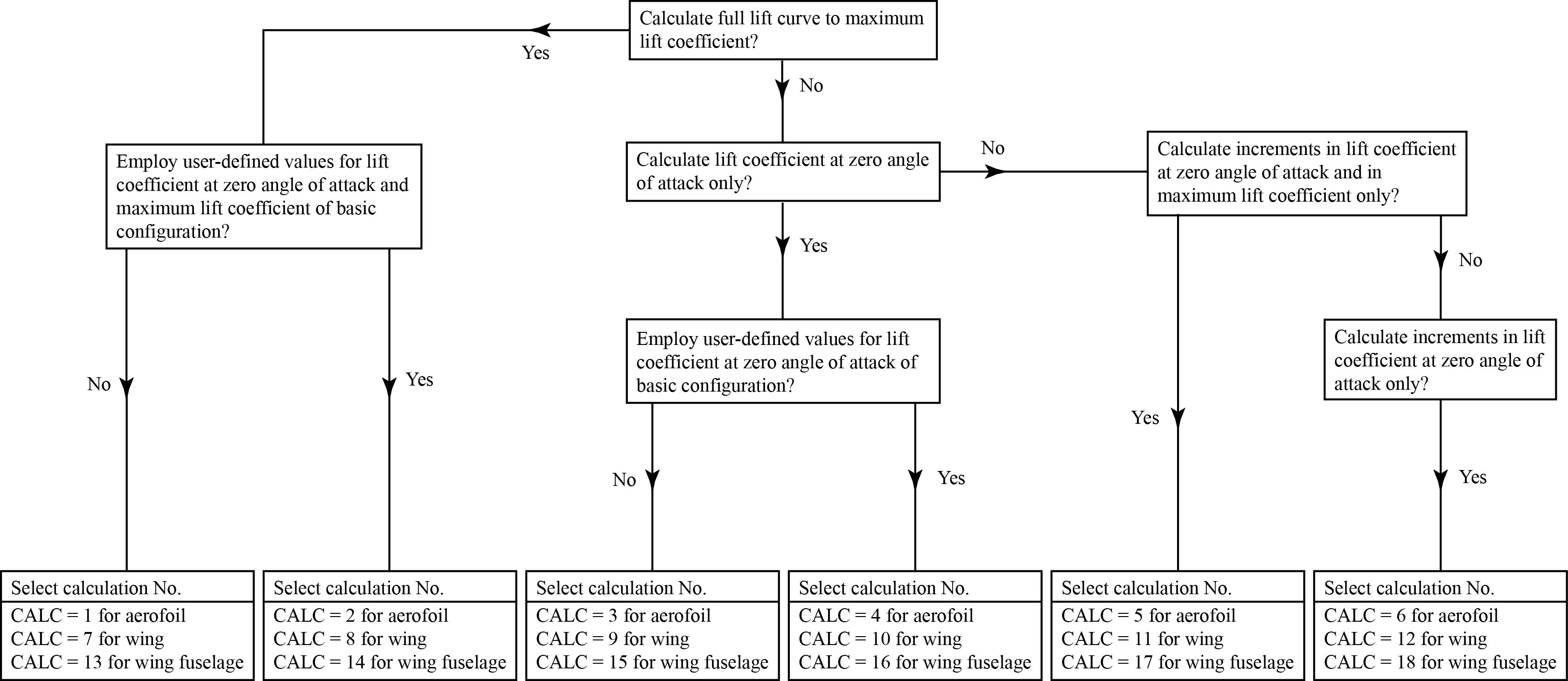
The user is allowed to select from a number of different types of run. Instead of calculating the whole lift curve, a run may be restricted to the calculation of the lift coefficient at zero angle of attack or to the calculation of the increment in the lift coefficient at zero angle of attack due to the deployment of high-lift devices, with or without the calculation of the increment in maximum lift coefficient. There is also a provision for user-defined lift coefficients to be used for the basic aerofoil, wing or wing-fuselage combination in place of the calculated values. Table 3.1 associates each type of run with an integer value of the Calc parameter, which is used as a switch in the program. The flow chart in Sketch 3.1 guides the user through the run selection process.
For wing and wing-fuselage combinations, calculations of the increments due to device deployment require section data at the mid-span of each device panel, see Sketch 1.3. Where needed in the calculation of the increments in maximum lift coefficient, the program automatically converts section properties and leading-edge device deflection angles to those normal to the leading edge and converts trailing-edge flap deflection angles to those normal to the flap hinge-line. For calculations that do not include the estimation of increments in maximum lift coefficient fewer section data are required.
Table 3.1 Calculation Types
| Section type of calc | Target result(s) of calc | User-defined values for | |||||||||||
|---|---|---|---|---|---|---|---|---|---|---|---|---|---|
| Calc | Aerofoil | Wing | Wing-fuselage combination |
CL0wf CL0w or CL0 see Note |
CLmaxwf CLmaxw or CLm see Note |
Lift curve |
ΔCL0w or ΔCL0 only |
ΔCL0w ΔCLmax or ΔCL0 ΔCLm only |
CL0B or CL0Bw |
CLmaxB
or CLmB |
CL0Bf | CLmaxBf | ΔCLmaxf |
| 1 | ✔ | ✔ | ✔ | ✔ | |||||||||
| 2 | ✔ | ✔ | ✔ | ✔ | ✔ | ✔ | |||||||
| 3 | ✔ | ✔ | |||||||||||
| 4 | ✔ | ✔ | ✔ | ||||||||||
| 5 | ✔ | ✔ | |||||||||||
| 6 | ✔ | ✔ | |||||||||||
| 7 | ✔ | ✔ | ✔ | ✔ | |||||||||
| 8 | ✔ | ✔ | ✔ | ✔ | ✔ | ✔ | |||||||
| 9 | ✔ | ✔ | |||||||||||
| 10 | ✔ | ✔ | ✔ | ||||||||||
| 11 | ✔ | ✔ | |||||||||||
| 12 | ✔ | ✔ | |||||||||||
| 13 | ✔ | ✔ | ✔ | ✔ | ✔ | ||||||||
| 14 | ✔ | ✔ | ✔ | ✔ | ✔ | ✔ | |||||||
| 15 | ✔ | ✔ | |||||||||||
| 16 | ✔ | ✔ | ✔ | ||||||||||
| 17 | ✔ | ✔ | |||||||||||
| 18 | ✔ | ✔ | |||||||||||
| Note: | It is possible to run the program with no high-lift devices deployed, in which case only the properties of the basic wing-fuselage combination, wing or aerofoil, CL0Bf, CL0Bw, CL0B, CLmaxBf, CLmaxB or CLmB will be output. |
Sketch 3.1 Calculation Types
The different types of high-lift devices that may be selected are given in Table 3.2, together with the integers Nl or (Nl)j and Nt or (Nt)j that are used to identify them in the program input. In the new UI, devices are selected from a drop-down list in which they are identified by name.
Table 3.2 High-Lift Device Types
| Leading-edge device | Trailing-edge flap | ||
|---|---|---|---|
| Nl | Type | Nt | Type |
| 1 | plain flap | 1 | plain |
| 2 | droop | 2 | split |
| 3 | sealed slat | 3 | single-slotted |
| 4 | Krueger flap | 4 | double-slotted |
| 5 | slat | 5 | triple-slotted |
| 6 | vented Krueger flap | ||
The absence of leading-edge or trailing-edge devices is indicated by removing them from the GUI using the remove button

on the device panel, which has
the effect of setting the number of deflection angles, δl
or δt to zero.
Calculations may be carried out with different types of high-lift devices over different spanwise segments of a wing. For example, there could be a slotted trailing-edge flap panel over the inboard part of a wing and a plain trailing-edge flap panel outboard. There is an important restriction in the case of leading-edge devices: if the calculation is to include the prediction of maximum lift coefficient, there can be only a single device panel which must extend to the wing tip.
4. Input
Table 4.1 below provides detail of the inputs required for the various calculation types. Numerical values may be entered singly or, where appropriate, as comma-delimited lists.
Table 4.1 Program Inputs
| Input | Comments |
|---|---|
| Calc | Integer. Indicator for calculation type, selected from Table 3.1 or Sketch 3.1. |
| Mk Rk |
Pairs of Mach number and Reynolds number (subscript dropped in UI). 1 ≤ k ≤ 10 1 ≤ Mk ≤ 0.25; 0.7 ≤ Rk × 10−6 ≤ 9.0 (aerofoils) or ≤ 12.0 (wings)† |
| If Calc = 7 to 18: |
For a wing calculation, values of aspect ratio, taper ratio, fractional
chord line and sweep of nth-chord line (deg), 2 ≤ A ≤ 10, 0.1 ≤ λ ≤ 1.0, 0.0 ≤ n ≤ 1.0, 0 ≤ Λ0 ≤ 50°, tan−1[−2(1 λ)/(A(1 + λ))] |
| A λ n Λn | |
| If Calc = 7, 8, 11, 13, 14 or 17: |
Dimensionless spanwise location of peak loading on basic wing. There is no need to provide this value as there was in earlier versions of the program. Where required, it will be calculated automatically from the planform characteristics. |
| ηp | |
| If Calc = 1, 2, 4, 5, 6, 7, 8, 11, 13, 14 or 17: |
Indicator for presence of slotted trailing-edge flaps. There is no need to provide this explicitly as there was in earlier versions of the program. Where required, it will be inferred from the trailing-edge flap type(s). |
| TES |
| † |
For wings, the range 0.7 ≤ Rk × 10−6 ≤ 12.0
reflects the limits of the experimental database studied in the development of the method for CLmaxB, and previous versions
of the program would halt with an error message if that range were exceeded for Calc = 7, 8, 13 or 14. In the current version, the UI will not permit an input outside the allowed range. The methods in the program additionally require that 0.7 ≤ Rk (cp/c̿) cos2 Λ0 × 10−6 ≤ 12.0.↩ |
| Section properties of basic aerofoil or wing at ηp | |
| If Calc = 1, 3, 7 or 13 OR (if TES = 1 AND Calc = 2, 5, 8, 11, 14 or 17): | |
| Section Type* |
Indicator for category of section, selected from a drop-down list (see Section 3). Auto indicates that the program will decide, Modern indicates a modern section, Conventional indicates a conventional section. |
| t / c | Thickness to chord ratio, 0.06 ≤ t / c ≤ 0.24 |
| xtr / c | Dimensionless chordwise location of boundary-layer transition, 0.0 ≤ xtr / c ≤ 0.5 |
| xum / c zum / c | Dimensionless chordwise location and value of maximum upper-surface ordinate (see Sketch 1.1). |
| τ | Trailing-edge angle (in degrees) (see Sketch 1.1a), 0 ≤ τ ≤ 25° |
| (x / c)i (zu / c)i (zl / c)i | Section dimensionless upper-surface and lower-surface ordinates at each of 17 standard values of dimensionless chordwise location, (x / c)i = 0, 0.01, 0.0125, 0.025, 0.05, 0.1, 0.2, 0.3, 0.4, 0.5, 0.6, 0.7, 0.8, 0.9, 0.95, 0.99 and 1.0, for 1 ≤ i ≤ 17. |
| Restricted sets of section data for basic aerofoil. | |
| If TES = 0 AND Calc = 2: | |
|
t / c xtr / c τ τa τau xum / c zum / c (zu / c)5 (zl / c)5 |
Thickness to chord ratio, 0.06 ≤ t / c ≤ 0.24 Dimensionless chordwise location of boundary-layer transition, 0.0 ≤ xtr / c ≤ 0.5 Trailing-edge angle (in degrees) (see Sketch 1.1a), 0 ≤ τ ≤ 25° Trailing-edge angle (in degrees) (see Sketch 1.1b), 0 ≤ τa ≤ 25° Trailing-edge angle (in degrees) (see Sketch 1.1c), 0 ≤ τau ≤ 25° Dimensionless chordwise station and value of maximum upper-surface ordinate. Upper-surface and lower-surface ordinates at x / c = 0.05 |
| If TES = 1 AND Calc = 4 or 6: | |
|
t / c τ τa |
Thickness to chord ratio, 0.06 ≤ t / c ≤ 0.24 Trailing-edge angle (in degrees) (see Sketch 1.1a), 0 ≤ τ ≤ 25° Trailing-edge angle (in degrees) (see Sketch 1.1b), 0 ≤ τa ≤ 25° |
| * | Comments on Section Type selection, see Section 3, are output only for Calc = 1, 7 or 13 because it has no effect on Calc = 3 calculations, but is input for consistency of input format, and has only a small effect, through a basic-section datum, on the increment in maximum lift coefficient due to deployment of slotted flaps. ↩ |
| Further data are required for the calculation of CL0B for the basic aerofoil or CL0Bw for the basic wing. | |
| If Calc = 1 or 3: | |
| zc92 / zc50 | Ratio of camber ordinate at x = 0.92c to camber ordinate at x = 0.5c. (Entered as unity for an uncambered section.) |
| If Calc = 7, 9, 13 or 15: | |
|
δ2/3 Data for root (centre-line) section: (x / c)ri (zu / c)ri (zl / c)ri (zc92 / zc50)r Data for section at η = 2/3: (x / c)2/3i (zu / c)2/3i (zl / c)2/3i (zc92 / zc50)2/3 |
Geometric twist angle at η = 2/3, in degrees, relative to the root (centre-line) chord, positive nose-up. Section dimensionless upper-surface and lower-surface ordinates at each of 15 standard values of dimensionless chordwise location, (x / c)i = 0, 0.025, 0.05, 0.1, 0.2, 0.3, 0.4, 0.5, 0.6, 0.7, 0.8, 0.9, 0.95, 0.99 and 1.0, for 1 ≤ i ≤ 15. Ratio of camber ordinate at x = 0.92c to camber ordinate at x = 0.5c. (Entered as zero for an uncambered section.) Section dimensionless upper-surface and lower-surface ordinates at each of 15 standard values of dimensionless chordwise location, (x / c)i = 0, 0.025, 0.05, 0.1, 0.2, 0.3, 0.4, 0.5, 0.6, 0.7, 0.8, 0.9, 0.95, 0.99 and 1.0, for 1 ≤ i ≤ 15. Ratio of camber ordinate at x = 0.92c to camber ordinate at x = 0.5c. (Entered as zero for an uncambered section.) |
| The following data are only required where the presence of a fuselage is to be considered. | |
| If Calc = 13 to 18: | |
| Fuselage Interference | The fuselage effect on trailing-edge flap performance. Select Ignore or Include from the drop-down list. Where the effect is considered, it decreases linearly to zero as the gap between the fuselage side and the inboard panel limit increases from 0.005s to 0.05s. An interference effect is always included for a leading-edge device, whatever the choice for trailing-edge flaps provided the inboard gap is less than 0.005s, but is omitted otherwise. |
| W / s | Ratio of body width to wing semi-span (see Sketch 1.10). |
| iW | Setting angle of wing root (centre-line) chord with respect to centre-line of fuselage (in degrees) (see Sketch 1.10). |
| If the Fuselage Interference effect is included: | |
| h / H | Height of wing relative to fuselage height (see Sketch 1.10). |
| The following data are necessary if user-defined values are to be supplied. The quantities depend on the calculation procedure selected, see Table 3.1. Values are entered NMR times. | |
| If Calc = 2: | |
| CL0B CLmB | User-defined values of lift coefficient at zero angle of attack and of maximum lift coefficient for basic aerofoil. |
| If Calc = 4: | |
| CL0B | User-defined value of lift coefficient at zero angle of attack for basic aerofoil. |
| If Calc = 8: | |
| CL0Bw CLmaxB | User-defined values of lift coefficient at zero angle of attack and of maximum lift coefficient for basic wing. |
| If Calc = 10: | |
| CL0Bw | User-defined value of lift coefficient at zero angle of attack for basic wing. |
| If Calc = 13: | |
| ΔCLmaxf | User-defined value of effect of fuselage on maximum lift coefficient. |
| If Calc = 14: | |
| CL0Bf CLmaxBf | User-defined values of lift coefficient at zero angle of attack and of maximum lift coefficient for basic wing-fuselage combination. |
| If Calc = 16: | |
| CL0Bf | User-defined value of lift coefficient at zero angle of attack for basic wing-fuselage combination. |
| Numbers of high-lift system settings, Calc = 1 to 18: | |
| Nδl Nδt | Number of settings of leading-edge device and trailing-edge flap. Not required as explicit values in the UI version of the program, but the multiplicity of values provided for certain other geometric device parameters must correspond. Both are limited to a maximum of 10. |
| High-lift system specification for aerofoil, Calc = 1 to 6: | |
| Nl Nt | Identify leading-edge device and trailing-edge flap type, respectively. Not required as explicit integer values by the UI version of the program; instead, device types are selected by name from a drop-down list. See Table 3.2 for more information on device types. |
| High-lift system specification for wing, Calc = 7 to 18: | |
|
Nnl (Nl)j (ηil)j (ηol)j Nnt (Nt)j (ηit)j (ηot)j |
Number of leading-edge device panels. Not required as an explicit input by the UI version of the program. Only one LED panel is allowed for Calc = 7, 8, 11, 13, 14 or 17. Identifies leading-edge device type. Not required as explicit integer input by the UI version of the program; instead, device types are selected by name from a drop-down list. See Table 3.2 for more information on device types. Positions of the inboard and outboard limits, respectively, of each leading-edge device panel as a fraction of wing semi-span. For Calc = 7, 8, 11, 13, 14 or 17, only one LED is allowed, and it must extend to the wing-tip (ie (ηol)1 must = 1). Number of trailing-edge flap panels. Not required as an explicit input by the UI version of the program. Identifies trailing-edge flap type. Not required as explicit integer input by the UI version of the program; instead, device types are selected by name from a drop-down list. See Table 3.2 for more information on device types. Positions of the inboard and outboard limits, respectively, of each trailing-edge flap panel as a fraction of wing semi-span. |
| Leading-edge device data for aerofoil, Calc = 1, 2 or 5 (all data entered Nδl times): | |
| If Nl = 1: | Plain flap (See Sketch 1.4) |
|
δl ρl / c cl´ / c Δcl / c |
Deflection angle in degrees. Leading-edge radius as a fraction of chord length. Extended chord of leading-edge device as a fraction of chord length. Chord extension due to deployment of leading-edge device as a fraction of chord length. |
| If Nl = 2: | Droop (See Sketch 1.4) |
|
δl ρl / c cl´ / c Δcl / c |
Deflection angle in degrees. Leading-edge radius as a fraction of chord length. Extended chord of leading-edge device as a fraction of chord length. Chord extension due to deployment of leading-edge device as a fraction of chord length. |
| If Nl = 3: | Sealed slat (See Sketch 1.5) |
|
δl ρl / c cl´ / c Δcl / c Hl / c |
Deflection angle in degrees. Leading-edge radius as a fraction of chord length. Extended chord of leading-edge device as a fraction of chord length. Chord extension due to deployment of leading-edge device as a fraction of chord length. Height of slat trailing edge above chord line as a fraction of chord length. |
| If Nl = 4: | Krueger (See Sketch 1.5) |
|
δl ρl / c cl´ / c Δcl / c Hl / c |
Deflection angle in degrees. Leading-edge radius as a fraction of chord length.* Extended chord of leading-edge device as a fraction of chord length. Chord extension due to deployment of leading-edge device as a fraction of chord length. Height of Krueger trailing edge above chord line as a fraction of chord length. |
| If Nl = 5: | Slat (See Sketch 1.6) |
|
δl ρl / c cl / c Δcl / c Gl / c Hl / c Ll / c xl / c xn / c |
Deflection angle in degrees. Leading-edge radius as a fraction of chord length. Chord of leading-edge device as a fraction of chord length.† Chord extension due to deployment of leading-edge device as a fraction of chord length. Normal distance between slat trailing-edge and section surface as a fraction of chord length. Height of slat trailing edge above chord line as a fraction of chord length.‡ Overlap between deployed slat and fixed-section nose as a fraction of chord length. Chordwise location of undeployed slat trailing edge as a fraction of chord length. Chordwise location of fixed section nose as a fraction of chord length. |
| If Nl = 6: | Vented Krueger (See Sketch 1.6) |
|
δl ρl / c cl / c Δcl / c Gl / c Hl / c Ll / c |
Deflection angle in degrees. Leading-edge radius as a fraction of chord length.* Chord of leading-edge device as a fraction of chord length.† Chord extension due to deployment of leading-edge device as a fraction of chord length. Normal distance between slat trailing-edge and section surface as a fraction of chord length. Height of Krueger trailing edge above chord line as a fraction of chord length.‡ Overlap between deployed Krueger and fixed-section nose as a fraction of chord length.‡ |
| * | Note that for Krüger flaps the underlying methods assume that their leading-edge radius is the same as that of the basic aerofoil; see Section 4.3 of ESDU 9402710 and Section 4.1 of this guide. ↩ |
| † | Note that for slats and vented Krüger flaps the device chord to section chord ratio, cl / c, is input but for the other leading-edge devices the extended device chord to section chord ratio, cl´ / c is required. ↩ |
| ‡ | Needed only for a check on the range of applicability. To maintain the same input style for all devices, Δcl / c is read as input; Equations (1.5a) and (1.5b) are not programmed. ↩ |
| Trailing-edge flap data for aerofoil, Calc = 1, 2 or 5: | |
| If Nt = 1: | Plain flap (See Sketch 1.7) |
|
Enter Nδt times: δt Δct / c Enter once per device panel: ct / c ρl / t ϕt |
Deflection angle in degrees. Chord extension due to deployment as a fraction of chord length. Flap chord as a fraction of chord length. Leading-edge radius of section or of deployed leading-edge device as a fraction of thickness, 0.04 ≤ ρl / t ≤ 0.14 Angle between aerofoil datum and tangent to upper surface at trailing edge (in degrees). |
| If Nt = 2: | Split flap (See Sketches 1.8 and 1.1d) |
|
Enter Nδt times: δt Δct / c Enter once per device panel: ct / c xlm / c zlm / c zcm / c (zu / c)1.25 (zl / c)1.25 |
Deflection angle in degrees. Chord extension due to deployment as a fraction of chord length. Flap chord as a fraction of chord length. Chordwise location of section maximum lower-surface ordinate as a fraction of chord length. Section maximum (negative) lower-surface ordinate as a fraction of chord length. Section maximum camber height as a fraction of chord length. Section upper-surface ordinate at x = 0.0125c as a fraction of chord length. Section lower-surface ordinate at x = 0.0125c as a fraction of chord length. |
| If Nt = 3: | Single-slotted flap (See Sketch 1.9a) |
|
Enter Nδt times: δt1 Δct1 / c Enter once per device panel: ct1 / c xts / c |
Deflection angle in degrees. Chord extension due to deployment as a fraction of chord length. Flap chord as a fraction of chord length. Chordwise location of flap shroud trailing edge as a fraction of chord length. |
| If Nt = 4: | Double-slotted flap (See Sketch 1.9b) |
|
Enter Nδt times: δt1, δt2 Δct1 / c, Δct2 / c Enter once per device panel: ct1 / c, ct2 / c xts / c |
Deflection angle in degrees of first and second elements. Chord extension due to deployment of first and second elements as a fraction of chord length. Flap chord of first and second elements as a fraction of chord length. Chordwise location of flap shroud trailing edge as a fraction of chord length. |
| If Nt = 5: | Triple-slotted flap (See Sketch 1.9c) |
|
Enter Nδt times: δt1, δt2, δt3 Δct1 / c, Δct2 / c, Δct3 / c Enter once per device panel: ct1 / c, ct2 / c, ct3 / c xts / c |
Deflection angle in degrees of first, second and third elements. Chord extension due to deployment of first, second and third elements as a fraction of chord length. Flap chord of first, second and third elements as a fraction of chord length. Chordwise location of flap shroud trailing edge as a fraction of chord length. |
| Leading-edge device data for aerofoil, Calc = 3, 4 or 6 (all data entered Nδl times): | |
| If Nl = 1: | Plain flap (See Sketch 1.4) |
|
δl cl´ / c Δcl / c |
Deflection angle in degrees. Extended chord of leading-edge device as a fraction of chord length. Chord extension due to deployment of leading-edge device as a fraction of chord length. |
| If Nl = 2: | Droop (See Sketch 1.4) |
|
δl cl´ / c Δcl / c |
Deflection angle in degrees. Extended chord of leading-edge device as a fraction of chord length. Chord extension due to deployment of leading-edge device as a fraction of chord length. |
| If Nl = 3: | Sealed slat (See Sketch 1.5) |
|
δl cl´ / c Δcl / c |
Deflection angle in degrees. Extended chord of leading-edge device as a fraction of chord length. Chord extension due to deployment of leading-edge device as a fraction of chord length. |
| If Nl = 4: | Krueger (See Sketch 1.5) |
|
δl cl´ / c Δcl / c |
Deflection angle in degrees. Extended chord of leading-edge device as a fraction of chord length. Chord extension due to deployment of leading-edge device as a fraction of chord length. |
| If Nl = 5: | Slat (See Sketch 1.6) |
|
δl cl / c Δcl / c |
Deflection angle in degrees. Chord of leading-edge device as a fraction of chord length.† Chord extension due to deployment of leading-edge device as a fraction of chord length. |
| If Nl = 6: | Vented Krueger (See Sketch 1.6) |
|
δl cl / c Δcl / c |
Deflection angle in degrees. Chord of leading-edge device as a fraction of chord length.† Chord extension due to deployment of leading-edge device as a fraction of chord length. |
| † | Note that for slats and vented Krüger flaps the device chord to section chord ratio, cl / c, is input but for the other leading-edge devices the extended device chord to section chord ratio, cl´ / c is required. ↩ |
| Trailing-edge flap data for aerofoil, Calc = 3, 4 or 6: | |
| If Nt = 1: | Plain flap (See Sketch 1.7) |
|
Enter Nδt times: δt Δct / c Enter once per device panel: ct / c ϕt |
Deflection angle in degrees. Chord extension due to deployment as a fraction of chord length. Flap chord as a fraction of chord length. Angle between aerofoil datum and tangent to upper surface at trailing edge (in degrees). |
| If Nt = 2: | Split flap (See Sketches 1.8 and 1.1d) |
|
Enter Nδt times: δt Δct / c Enter once per device panel: ct / c xlm / c zlm / c |
Deflection angle in degrees. Chord extension due to deployment as a fraction of chord length. Flap chord as a fraction of chord length. Chordwise location of section maximum lower-surface ordinate as a fraction of chord length. Section maximum (negative) lower-surface ordinate as a fraction of chord length. |
| If Nt = 3: | Single-slotted flap (See Sketch 1.9a) |
|
Enter Nδt times: δt1 Δct1 / c Enter once per device panel: ct1 / c xts / c |
Deflection angle in degrees. Chord extension due to deployment as a fraction of chord length. Flap chord as a fraction of chord length. Chordwise location of flap shroud trailing edge as a fraction of chord length. |
| If Nt = 4: | Double-slotted flap (See Sketch 1.9b) |
|
Enter Nδt times: δt1, δt2 Δct1 / c, Δct2 / c Enter once per device panel: ct1 / c, ct2 / c xts / c |
Deflection angle in degrees of first and second elements. Chord extension due to deployment of first and second elements as a fraction of chord length. Flap chord of first and second elements as a fraction of chord length. Chordwise location of flap shroud trailing edge as a fraction of chord length. |
| If Nt = 5: | Triple-slotted flap (See Sketch 1.9c) |
|
Enter Nδt times: δt1, δt2, δt3 Δct1 / c, Δct2 / c, Δct3 / c Enter once per device panel: ct1 / c, ct2 / c, ct3 / c xts / c |
Deflection angle in degrees of first, second and third elements. Chord extension due to deployment of first, second and third elements as a fraction of chord length. Flap chord of first, second and third elements as a fraction of chord length. Chordwise location of flap shroud trailing edge as a fraction of chord length. |
| Section geometry of high-lift system at mid-span of device panel(s) for Calc = 7, 8, 11, 13, 14 or 17: | |
|
Leading-edge device data at mid-span of device panel, Calc = 7, 8, 11, 13, 14 or 17 (all data entered Nδl times) Only one panel permitted: |
|
| If (Nl)j = 1: | Plain flap (See Sketch 1.4) |
|
(δl)j (ρl / c)j (cl´ / c)j (Δcl / c)j |
Deflection angle in degrees. Leading-edge radius as a fraction of chord length. Extended chord of leading-edge device as a fraction of chord length. Chord extension due to deployment of leading-edge device as a fraction of chord length. |
| If Nl = 2: | Droop (See Sketch 1.4) |
|
(δl)j (ρl / c)j (cl´ / c)j (Δcl / c)j |
Deflection angle in degrees. Leading-edge radius as a fraction of chord length. Extended chord of leading-edge device as a fraction of chord length. Chord extension due to deployment of leading-edge device as a fraction of chord length. |
| If Nl = 3: | Sealed slat (See Sketch 1.5) |
|
(δl)j (ρl / c)j (cl´ / c)j (Δcl / c)j (Hl / c)j |
Deflection angle in degrees. Leading-edge radius as a fraction of chord length. Extended chord of leading-edge device as a fraction of chord length. Chord extension due to deployment of leading-edge device as a fraction of chord length. Height of slat trailing edge above chord line as a fraction of chord length. |
| If Nl = 4: | Krueger (See Sketch 1.5) |
|
(δl)j (ρl / c)j (cl´ / c)j (Δcl / c)j (Hl / c)j |
Deflection angle in degrees. Leading-edge radius as a fraction of chord length.* Extended chord of leading-edge device as a fraction of chord length. Chord extension due to deployment of leading-edge device as a fraction of chord length. Height of Krueger trailing edge above chord line as a fraction of chord length. |
| If Nl = 5: | Slat (See Sketch 1.6) |
|
(δl)j (ρl / c)j (cl / c)j (Δcl / c)j (Gl / c)j (Hl / c)j (Ll / c)j (xl / c)j (xn / c)j |
Deflection angle in degrees. Leading-edge radius as a fraction of chord length. Chord of leading-edge device as a fraction of chord length.† Chord extension due to deployment of leading-edge device as a fraction of chord length. Normal distance between slat trailing-edge and section surface as a fraction of chord length. Height of slat trailing edge above chord line as a fraction of chord length.‡ Overlap between deployed slat and fixed-section nose as a fraction of chord length. Chordwise location of undeployed slat trailing edge as a fraction of chord length. Chordwise location of fixed section nose as a fraction of chord length. |
| If Nl = 6: | Vented Krueger (See Sketch 1.6) |
|
(δl)j (ρl / c)j (cl / c)j (Δcl / c)j (Gl / c)j (Hl / c)j (Ll / c)j |
Deflection angle in degrees. Leading-edge radius as a fraction of chord length.* Chord of leading-edge device as a fraction of chord length.† Chord extension due to deployment of leading-edge device as a fraction of chord length. Normal distance between slat trailing-edge and section surface as a fraction of chord length. Height of Krueger trailing edge above chord line as a fraction of chord length.‡ Overlap between deployed Krueger and fixed-section nose as a fraction of chord length.‡ |
| * | Note that for Krüger flaps the underlying methods assume that their leading-edge radius is the same as that of the basic aerofoil; see Section 4.3 of ESDU 9402710 and Section 4.1 of this guide. ↩ |
| † | Note that for slats and vented Krüger flaps the device chord to section chord ratio, cl / c, is input but for the other leading-edge devices the extended device chord to section chord ratio, cl´ / c is required. ↩ |
| ‡ | Needed only for a check on the range of applicability. To maintain the same input style for all devices, Δcl / c is read as input; Equations (1.5a) and (1.5b) are not programmed. ↩ |
|
Trailing-edge flap data at mid-span of each panel, Calc = 7, 8, 11, 13, 14 or 17. Up to 5 panels permitted: |
|
| If Nt = 1: | Plain flap (See Sketch 1.7) |
|
Enter Nδt times: (δt)j (Δct / c)j Enter once per device panel: (ct / c)j (ρl / t)j (ϕt)j (Λh)j |
Deflection angle in degrees. Chord extension due to deployment as a fraction of chord length. Flap chord as a fraction of chord length. Leading-edge radius of section or of deployed leading-edge device as a fraction of thickness, 0.04 ≤ ρl / t ≤ 0.14 Angle between aerofoil datum and tangent to upper surface at trailing edge (in degrees). Hinge-line sweep (in degrees), −8° ≤ Λh ≤ 50° |
| If Nt = 2: | Split flap (See Sketches 1.8 and 1.1d) |
|
Enter Nδt times: (δt)j (Δct / c)j Enter once per device panel: (ct / c)j (xlm / c)j (zlm / c)j (zcm / c)j ((zu / c)1.25)j ((zl / c)1.25)j (Λh)j |
Deflection angle in degrees. Chord extension due to deployment as a fraction of chord length. Flap chord as a fraction of chord length. Chordwise location of section maximum lower-surface ordinate as a fraction of chord length. Section maximum (negative) lower-surface ordinate as a fraction of chord length. Section maximum camber height as a fraction of chord length. Section upper-surface ordinate at x = 0.0125c as a fraction of chord length. Section lower-surface ordinate at x = 0.0125c as a fraction of chord length. Hinge-line sweep (in degrees), −8° ≤ Λh ≤ 50° |
| If Nt = 3: | Single-slotted flap (See Sketch 1.9a) |
|
Enter Nδt times: (δt1)j (Δct1 / c)j Enter once per device panel: (ct1 / c)j (xts / c)j (Λh)j |
Deflection angle in degrees. Chord extension due to deployment as a fraction of chord length. Flap chord as a fraction of chord length. Chordwise location of flap shroud trailing edge as a fraction of chord length. Hinge-line sweep (in degrees), −8° ≤ Λh ≤ 50° |
| If Nt = 4: | Double-slotted flap (See Sketch 1.9b) |
|
Enter Nδt times: (δt1)j, (δt2)j (Δct1 / c)j, (Δct2 / c)j Enter once per device panel: (ct1 / c)j, (ct2 / c)j (xts / c)j (Λh)j |
Deflection angle in degrees of first and second elements. Chord extension due to deployment of first and second elements as a fraction of chord length. Flap chord of first and second elements as a fraction of chord length. Chordwise location of flap shroud trailing edge as a fraction of chord length. Hinge-line sweep (in degrees), −8° ≤ Λh ≤ 50° |
| If Nt = 5: | Triple-slotted flap (See Sketch 1.9c) |
|
Enter Nδt times: (δt1)j, (δt2)j, (δt3)j (Δct1 / c)j, (Δct2 / c)j, (Δct3 / c)j Enter once per device panel: (ct1 / c)j, (ct2 / c)j, (ct3 / c)j (xts / c)j (Λh)j |
Deflection angle in degrees of first, second and third elements. Chord extension due to deployment of first, second and third elements as a fraction of chord length. Flap chord of first, second and third elements as a fraction of chord length. Chordwise location of flap shroud trailing edge as a fraction of chord length. Hinge-line sweep (in degrees), −8° ≤ Λh ≤ 50° |
| Section geometry of high-lift system at mid-span of device panel(s) for Calc = 9, 10, 12, 15, 16 or 18: | |
|
Leading-edge device data at mid-span of device panel, Calc = 9, 10, 12, 15, 16 or 18 (all data entered Nδl times). Up to 5 panels permitted: |
|
| If (Nl)j = 1: | Plain flap (See Sketch 1.4) |
|
(δl)j (cl´ / c)j (Δcl / c)j |
Deflection angle in degrees. Extended chord of leading-edge device as a fraction of chord length. Chord extension due to deployment of leading-edge device as a fraction of chord length. |
| If Nl = 2: | Droop (See Sketch 1.4) |
|
(δl)j (cl´ / c)j (Δcl / c)j |
Deflection angle in degrees. Extended chord of leading-edge device as a fraction of chord length. Chord extension due to deployment of leading-edge device as a fraction of chord length. |
| If Nl = 3: | Sealed slat (See Sketch 1.5) |
|
(δl)j (cl´ / c)j (Δcl / c)j |
Deflection angle in degrees. Extended chord of leading-edge device as a fraction of chord length. Chord extension due to deployment of leading-edge device as a fraction of chord length. |
| If Nl = 4: | Krueger (See Sketch 1.5) |
|
(δl)j (cl´ / c)j (Δcl / c)j |
Deflection angle in degrees. Extended chord of leading-edge device as a fraction of chord length. Chord extension due to deployment of leading-edge device as a fraction of chord length. |
| If Nl = 5: | Slat (See Sketch 1.6) |
|
(δl)j (cl / c)j (Δcl / c)j |
Deflection angle in degrees. Chord of leading-edge device as a fraction of chord length.† Chord extension due to deployment of leading-edge device as a fraction of chord length. |
| If Nl = 6: | Vented Krueger (See Sketch 1.6) |
|
(δl)j (cl / c)j (Δcl / c)j |
Deflection angle in degrees. Chord of leading-edge device as a fraction of chord length.† Chord extension due to deployment of leading-edge device as a fraction of chord length. |
| † | Note that for slats and vented Krüger flaps the device chord to section chord ratio, cl / c, is input but for the other leading-edge devices the extended device chord to section chord ratio, cl´ / c is required. ↩ |
|
Trailing-edge flap data at mid-span of each panel, Calc = 9, 10, 12, 15, 16 or 18. Up to 5 panels permitted: |
|
| If Nt = 1: | Plain flap (See Sketch 1.7) |
|
Enter Nδt times: (δt)j (Δct / c)j Enter once per device panel: (ct / c)j (ϕt)j |
Deflection angle in degrees. Chord extension due to deployment as a fraction of chord length. Flap chord as a fraction of chord length. Angle between aerofoil datum and tangent to upper surface at trailing edge (in degrees). |
| If Nt = 2: | Split flap (See Sketches 1.8 and 1.1d) |
|
Enter Nδt times: (δt)j (Δct / c)j Enter once per device panel: (ct / c)j (xlm / c)j (zlm / c)j |
Deflection angle in degrees. Chord extension due to deployment as a fraction of chord length. Flap chord as a fraction of chord length. Chordwise location of section maximum lower-surface ordinate as a fraction of chord length. Section maximum (negative) lower-surface ordinate as a fraction of chord length. |
| If Nt = 3: | Single-slotted flap (See Sketch 1.9a) |
|
Enter Nδt times: (δt1)j (Δct1 / c)j Enter once per device panel: (ct1 / c)j (xts / c)j |
Deflection angle in degrees. Chord extension due to deployment as a fraction of chord length. Flap chord as a fraction of chord length. Chordwise location of flap shroud trailing edge as a fraction of chord length. |
| If Nt = 4: | Double-slotted flap (See Sketch 1.9b) |
|
Enter Nδt times: (δt1)j, (δt2)j (Δct1 / c)j, (Δct2 / c)j Enter once per device panel: (ct1 / c)j, (ct2 / c)j (xts / c)j |
Deflection angle in degrees of first and second elements. Chord extension due to deployment of first and second elements as a fraction of chord length. Flap chord of first and second elements as a fraction of chord length. Chordwise location of flap shroud trailing edge as a fraction of chord length. |
| If Nt = 5: | Triple-slotted flap (See Sketch 1.9c) |
|
Enter Nδt times: (δt1)j, (δt2)j, (δt3)j (Δct1 / c)j, (Δct2 / c)j, (Δct3 / c)j Enter once per device panel: (ct1 / c)j, (ct2 / c)j, (ct3 / c)j (xts / c)j |
Deflection angle in degrees of first, second and third elements. Chord extension due to deployment of first, second and third elements as a fraction of chord length. Flap chord of first, second and third elements as a fraction of chord length. Chordwise location of flap shroud trailing edge as a fraction of chord length. |
5. Output
The main equations evaluated in the program are as follows:
For Aerofoils
| CL0 = CL0B + ΔCL0 | (5.1) | |
| with | ΔCL0 = ΔCL0l + ΔCL0t | (5.2) |
| and | CLm = CLmB + ΔCLm | (5.3) |
| with | ΔCLm = ΔCLml + ΔCLmt | (5.4) |
For Wings
| CL0w = CL0Bw + ΔCL0w | (5.5) | |||||||||||||||||||||
| with | ΔCL0w = ΔCL0lw + ΔCL0tw | (5.6) | ||||||||||||||||||||
|
(5.7) | |||||||||||||||||||||
| and | CLmaxw = CLmaxB + ΔCLmax | (5.8) | ||||||||||||||||||||
| with | ΔCLmax = ΔCLmaxl + ΔCLmaxt | (5.9) | ||||||||||||||||||||
|
(5.10)* |
For Wing-fuselage Combinations
| CL0wf = CL0Bf + ΔCL0w | (5.11) | |||||||||||||||||||||
| with | ΔCL0w = ΔCL0lw + ΔCL0tw | (5.12) | ||||||||||||||||||||
|
(5.13) | |||||||||||||||||||||
| and | CLmaxwf = CLmaxBf + ΔCLmax | (5.14) | ||||||||||||||||||||
| where | CLmaxBf = CLmaxB + ΔCLmaxf | (5.15) | ||||||||||||||||||||
| and | ΔCLmax = ΔCLmaxl + ΔCLmaxt | (5.16) | ||||||||||||||||||||
|
(5.17)* |
| * | Note that only a single leading-edge device (which must extend to the wing-tip) is permitted in calculations of increments in maximum lift for wings and wing-fuselage combinations. |
Lift Curve
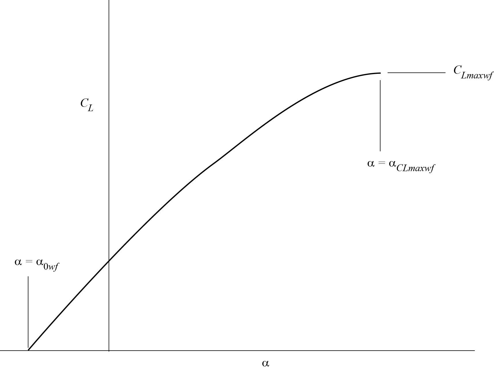
From the values of lift coefficient at zero angle of attack, the maximum lift coefficient and the initial linear value of the lift-curve slope the program uses the method of ESDU 9600316 to construct the non-linear lift curve from CL = 0 at the appropriate zero-lift angle up to maximum lift coefficient at the angle of attack for maximum lift, at quarter-degree intervals. The case for a wing-fuselage combination is illustrated in Sketch 5.1. It is possible that the constructed curve will extend to large negative angles of attack when trailing-edge flaps are deployed and values of CL for α < −5°, say, may not represent achievable conditions. Therefore the program outputs a warning in such cases and no values of lift coefficient are output between zero and the value at α = −10°.
Sketch 5.1 Lift Curve
6. Derivation and References
Derivation
The Derivation lists sources of information that have assisted in the preparation of this Guide.
| 1. | ESDU |
Slope of lift curve for two-dimensional flow. ESDU Aero W.01.01.05, 1955. |
|
| 2. | ESDU |
Aerodynamic characteristics of aerofoils in compressible inviscid
airflow at subcritical Mach numbers. ESDU 72024, 1972. |
|
| 3. | ESDU |
Aerofoil maximum lift coefficient for Mach numbers up to 0.4. ESDU 84026, 1984. |
|
| 4. | ESDU |
The maximum lift coefficient of plain wings at subsonic speeds. ESDU 89034, 1989. |
|
| 5. | ESDU |
Body effect on wing angle of attack and pitching moment at zero lift at
low speeds. ESDU 89042, 1989. |
|
| 6. | ESDU |
Maximum lift of wings with trailing-edge flaps at low speeds. ESDU 91014, 1991. |
|
| 7. | ESDU |
Maximum lift of wings with leading-edge devices and trailing-edge
flaps deployed. ESDU 92031, 1992. |
|
| 8. | ESDU |
Program for calculation of maximum lift coefficient of plain aerofoils
and wings at subsonic speeds. ESDU 93015, 1993. |
|
| 9. | ESDU |
Wing lift coefficient increment at zero angle of attack due to
deployment of single-slotted flaps at low speeds. ESDU 93019, 1993. |
|
| 10. | ESDU |
Increments in aerofoil lift coefficient at zero angle of attack and in
maximum lift coefficient due to deployment of various leading-edge
high-lift devices at low speeds. ESDU 94027, 1994. |
|
| 11. | ESDU |
Increments in aerofoil lift coefficient at zero angle of attack and in
maximum lift coefficient due to deployment of a plain trailing-edge
flap, with or without a leading-edge high-lift device, at low speeds. ESDU 94028, 1994. |
|
| 12. | ESDU |
Increments in aerofoil lift coefficient at zero angle of attack and in
maximum lift coefficient due to deployment of a trailing-edge split
flap, with or without a leading-edge high-lift device, at low speeds. ESDU 94029, 1994. |
|
| 13. | ESDU |
Increments in aerofoil lift coefficient at zero angle of attack and in
maximum lift coefficient due to deployment of a single-slotted
trailing-edge flap, with or without a leading-edge high-lift device, at
low speeds. ESDU 94030, 1995. |
|
| 14. | ESDU |
Increments in aerofoil lift coefficient at zero angle of attack and in
maximum lift coefficient due to deployment of a double-slotted or
triple-slotted trailing-edge flap, with or without a leading-edge high-lift
device, at low speeds. ESDU 94031, 1995. |
|
| 15. | ESDU |
Wing lift coefficient increment at zero angle of attack due to
deployment of double-slotted or triple-slotted flaps at low speeds. ESDU 95021, 1995. |
|
| 16. | ESDU |
Lift curve of wings with high-lift devices deployed at low speeds. ESDU 96003, 1996. |
|
| 17. | ESDU |
Wing lift coefficient increment at zero angle of attack due to
deployment of leading-edge devices at low speeds. ESDU 96032, 1996. |
|
| 18. | ESDU |
Fuselage interference effects on flap characteristics. ESDU 97003, 1997. |
|
| 19. | ESDU |
Wing lift coefficient increment at zero angle of attack due to
deployment of split trailing-edge flaps at low speeds. ESDU 97009, 1997. |
|
| 20. | ESDU |
Wing lift coefficient increment at zero angle of attack due to
deployment of plain trailing-edge flaps at low speeds. ESDU 97011, 1997. |
|
| 21. | ESDU |
Slope of aerofoil lift-curve for subsonic two-dimensional flow. ESDU 97020, 1997. |
|
| 22. | ESDU |
Aerofoil incidence for zero lift in subsonic two-dimensional flow. ESDU 98011, 1998. |
References
The References are sources of information supplementary to that in this Guide.
| 23. | ESDU |
Boundaries of linear characteristics of cambered and twisted wings at
subcritical Mach numbers. ESDU 88030, 1988. |
|
| 24. | ESDU |
Information on the use of Data Items on high-lift devices. ESDU 97002, 1997. |